Connection Types
The available connection types are defined in the Account under Connection Types. By default, the following connection types or systems are defined:
- None
- Riser – Lazy Wave
- Riser - Catenary
- Jumper – Horizontal Z
- Jumper – Vertical M
- Jumper – Vertical N”
The Riser Generation and Jumper Generation sections further down describes the more special Connection Types that have additional settings and design parameters. The connection system options differs based on if you have connected topside to subsea asset (Riser), or subsea to subsea asset (Jumper).
None
This is the default connection type, which is undefined and is a regular spline construct that can be freely edited by the user by adding new connection points to the spline for curvature adjustments
Riser Lazy Wave
To create a lazy wave riser, you start with connecting your desired topside asset (FPSO, semi sub etc.) to your subsea asset e.g. riser base, SSIV, or similar. Or select a connection that is already created. This will bring up the Connection Attributes section in Project View as shown below:
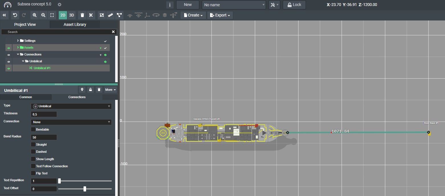
Then in the Connections tab you select the Connection drop down menu and pick Riser - Lazy Wave.
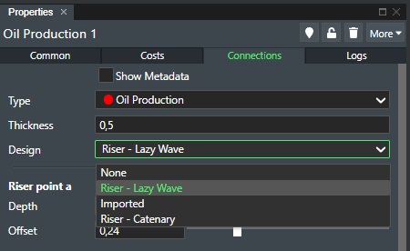
This will then display the riser properties for Lazy Wave riser generation.
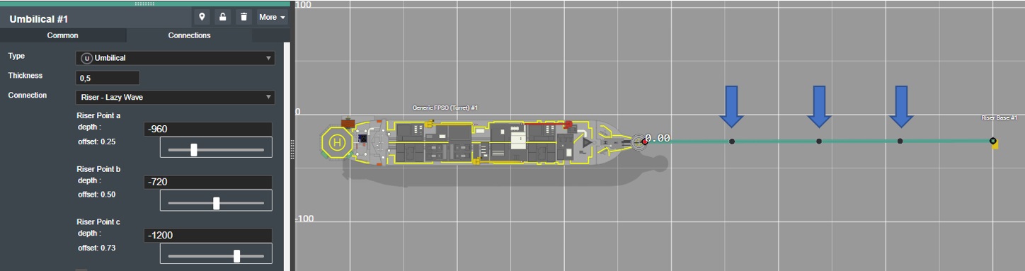
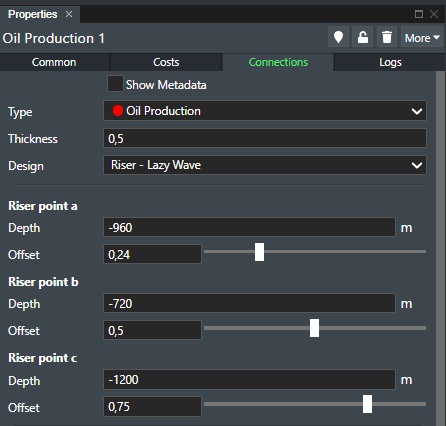
This will then generate three (3) riser control points on the connection. Switch to 3D to see how it looks. The Riser points are named a, b, and c. To control the Z value (depth) of the curvature points (A, B, and C) use the corresponding depth numerical input fields, including adjusting the offset for each curvature point. You can see the illustration below for more detail:
where the input fields are:
-
Depth - The numerical depth value (Z value) for each of the riser control points. The value range will be down to the sea bed level defined by project settings or loaded bathymetry.
-
Offset - The numerical offset value for each of the riser control points. The value range will is between 0.00 and 1.
Note! Control point C is the touchdown point.
Your riser creation will typically look as shown here:
You can of course also import risers from Engineering programs such as OrcaFlex through the Create Connection from File option.
Riser Catenary
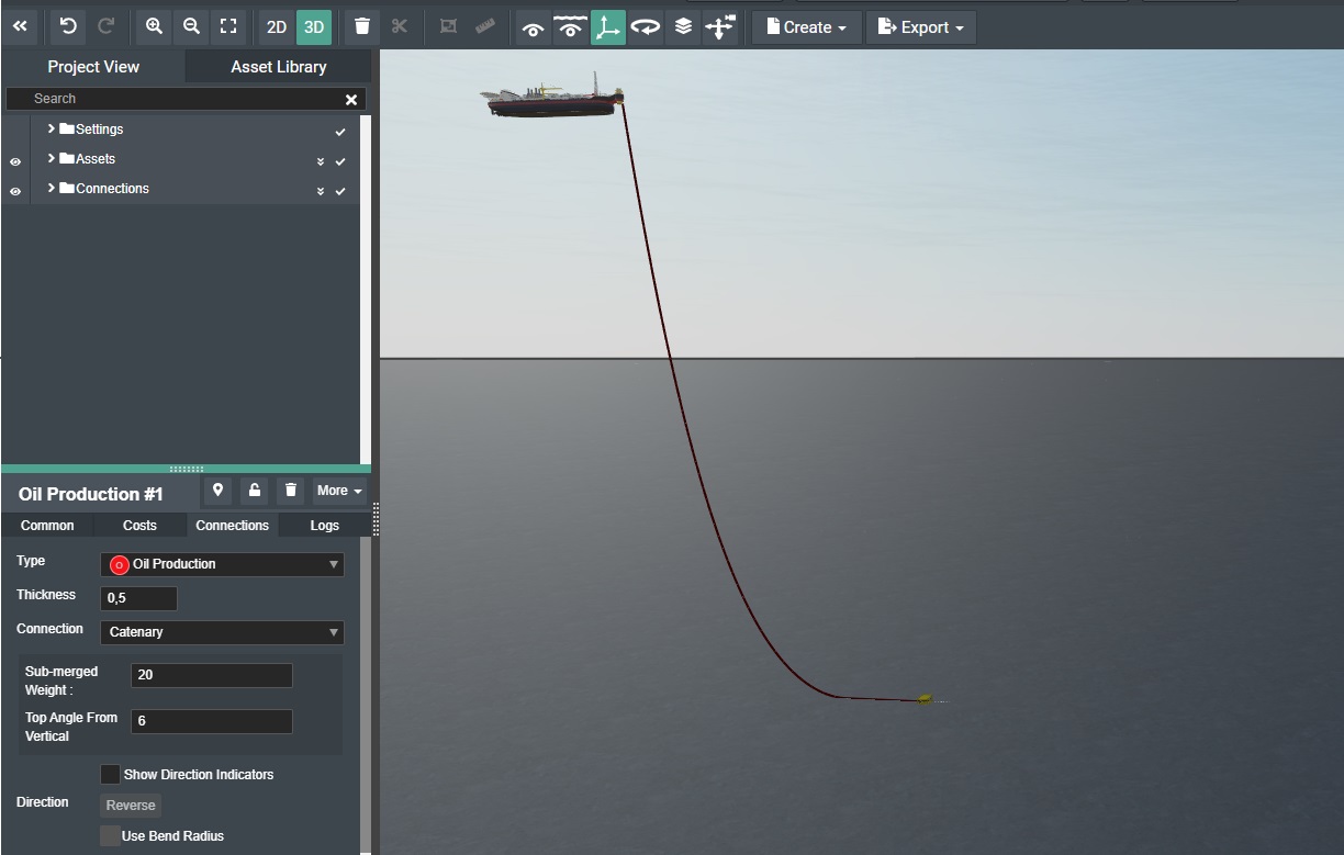
To create a catenary riser, you start with connecting your desired topside asset (FPSO, semi sub etc.) to your subsea asset e.g. riser base, SSIV, or similar. Or select a connection that is already created. This will bring up the Connection Attributes section in Project View as shown below:
Then in the Connections tab you select the Connection drop down menu and pick Riser - Catenary.
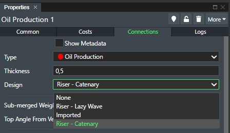
This will then display the riser properties for Catenary riser generation.
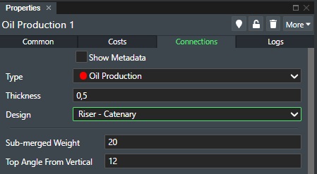
The catenary riser generation is formula based where the input fields are:
-
Sub-merged Weight - The numerical depth value of the submerged weight of the riser.
-
Top Angle From Vertical - Top angle in degrees.
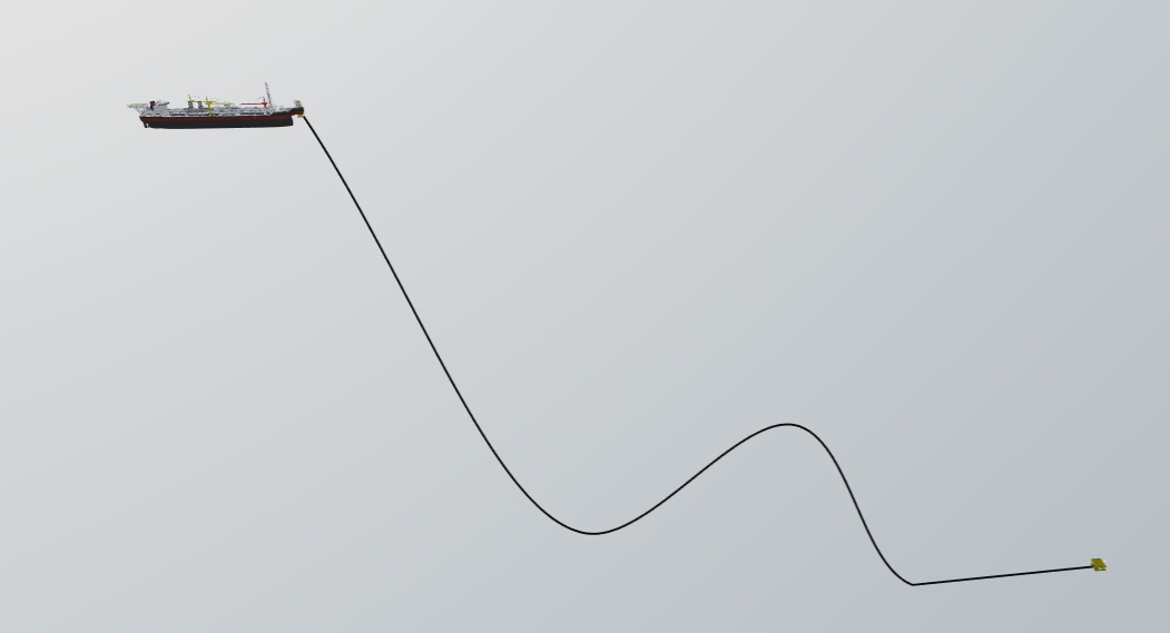
Once you are satisfied you can then switch to 3D view to see your riser creation as shown here:
You can of course also import risers from Engineering programs such as OrcaFlex through the Create Connection from File option.
Jumper Generation
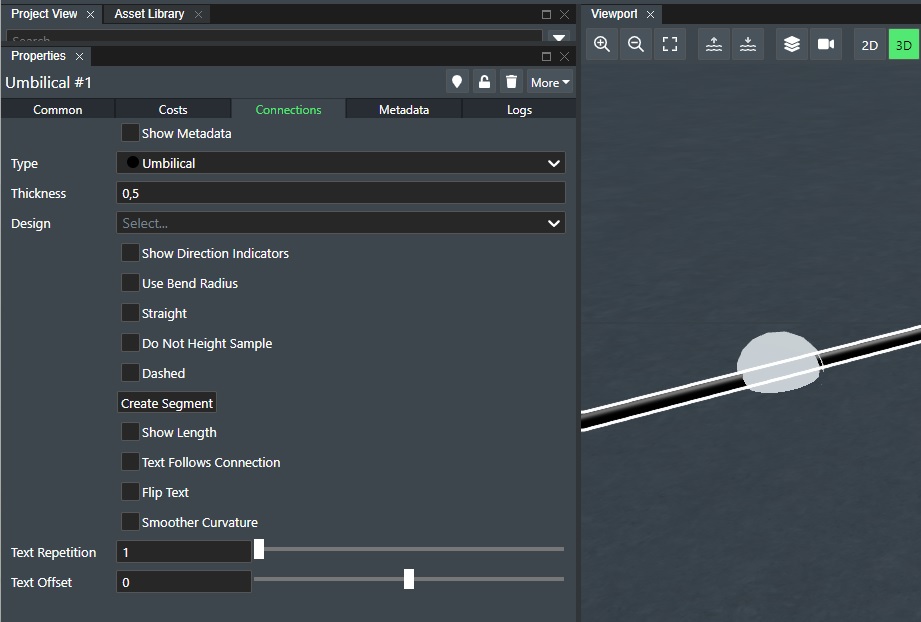
To create a jumper, you start with connecting your subsea to subsea asset e.g. XMT to a Manifold. Or select a connection that is already created. This will bring up the Connection Attributes section in Project View as shown below:
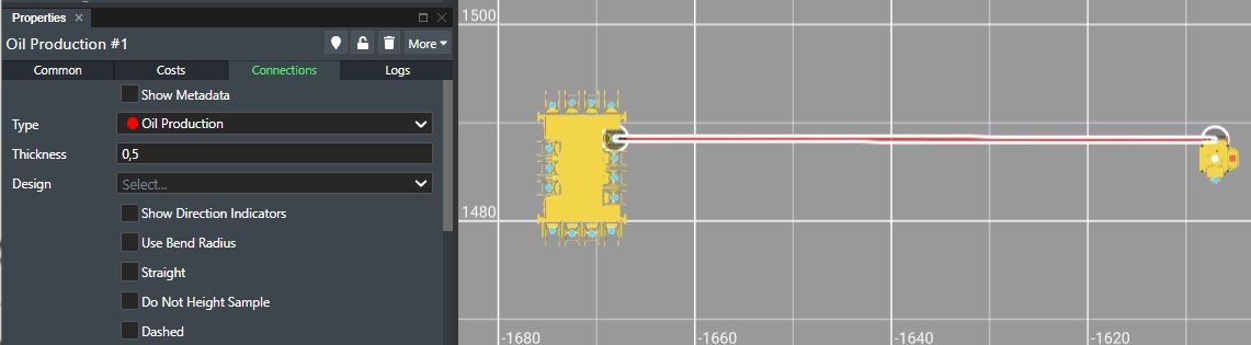
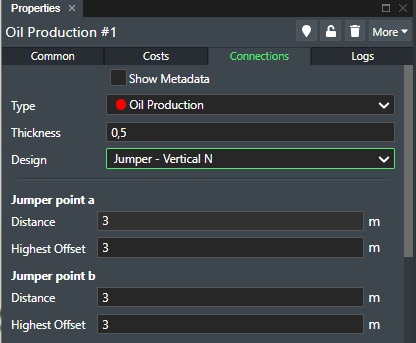
Then in the Connections tab you select the Connection drop down menu and the following options becomes available:
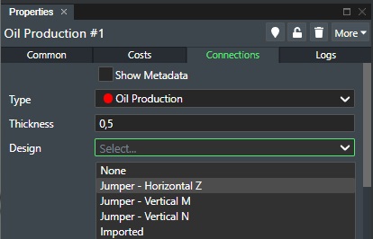
At the moment you can select between; Jumper - Vertical M, Jumper - Vertical N, and Jumper - Horizontal Z. Select the one you wish to use e.g. Jumper - Vertical M as shown here:
Jumper Vertical M
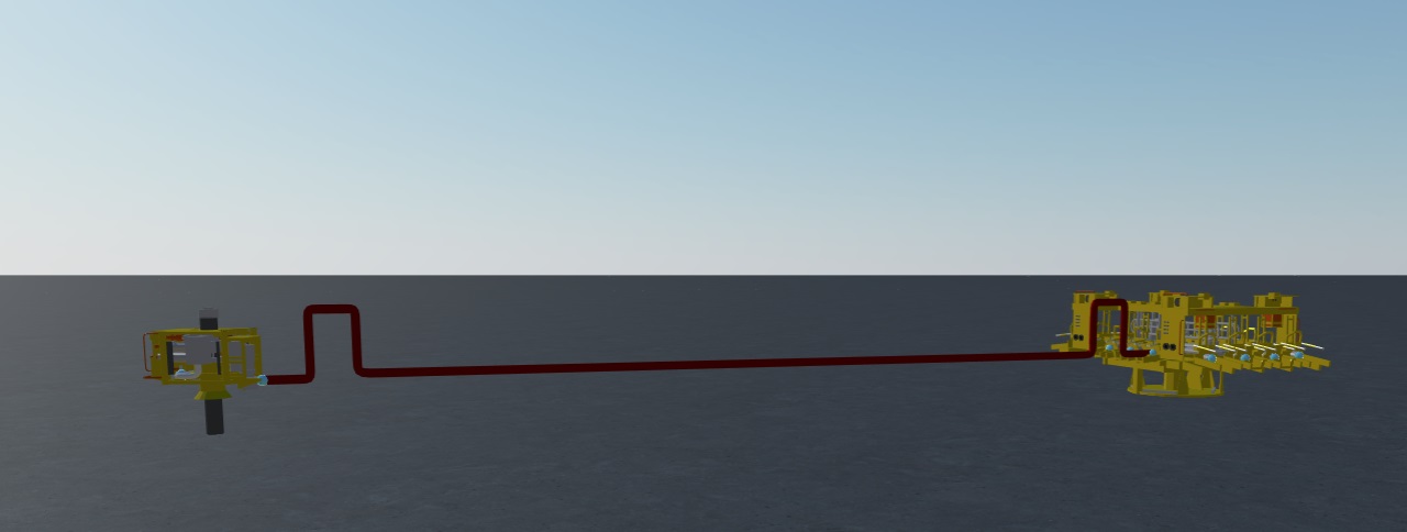
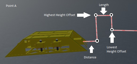
This jumper type has a set of parameters to adjust the jumper design to compensate for scenarios where the connected assets might be on different seabed elevation. See the illustration below:
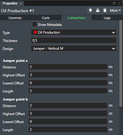
You have now the following jumper edit points for Jumper Point a and Jumper Point b as shown here and exaggerated for illustration purposes:
-
Distance - Adjust the numerical value for the distance up and down for the segment shown in the illustration above.
-
Highest Height Offset - Adjust the numerical value for the highest height offset up and down for the segment shown in the illustration above.
-
Lowest Height Offset - Adjust the numerical value for the lowest height offset up and down for the segment shown in the illustration above.
-
Length - Adjust the numerical value for the length up and down for the segment shown in the illustration above.
The Jumper Point b values are identical for the other side of the M Jumper Connection.
Note! - In the case of different height offsets between the connected assets as shown in the following illustration below:
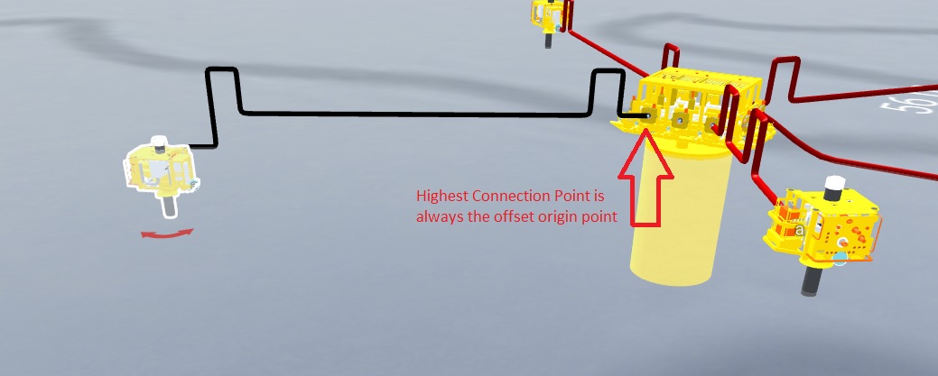
For the illustration above the highest connection point is always the the default offset origin when adjusting the Heigh Offset parameters. The calculation looks as follows:
const heightA = designParameters.a.highestHeightDelta
const heightB = designParameters.b.highestHeightDelta
const highestZ = Math.max(a.z, b.z)

const ah = new Vector3(a.x, a.y, highestZ + heightA)
const bh = new Vector3(b.x, b.y, highestZ + heightB)
const abh = new Vector3(a.x, a.y, highestZ + heightB)

const highestZ = Math.max(a.z, b.z)
Jumper Vertical N
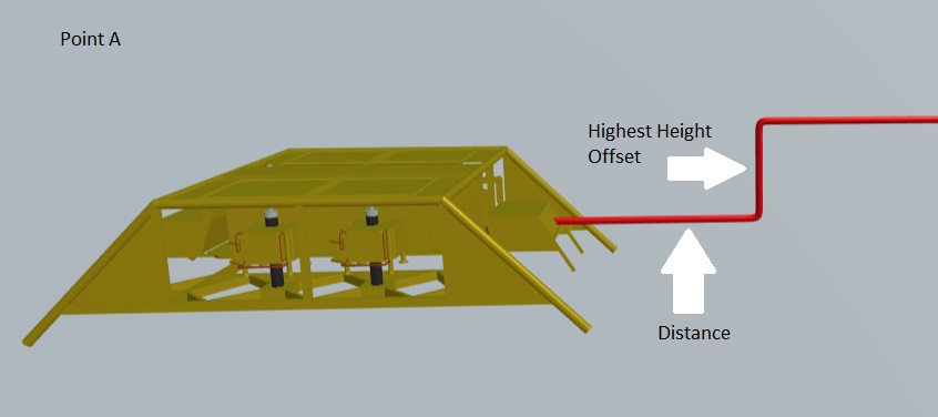
This jumper type has a set of parameters to adjust the jumper design to compensate for scenarios where the connected assets might be on different seabed elevation. See the illustration below:
You have now the following jumper edit points for Jumper Point a and Jumper Point b as shown here and exaggerated for illustration purposes:
-
Distance - Adjust the numerical value for the distance up and down for the segment shown in the illustration above.
-
Highest Height Offset - Adjust the numerical value for the highest height offset up and down for the segment shown in the illustration above.
The Jumper Point b values are identical for the other side of the N Jumper Connection.
Jumper Horizontal Z
This jumper type has a set of parameters to adjust the jumper design to compensate for scenarios where the connected assets might be on different seabed elevation. See the illustration below:
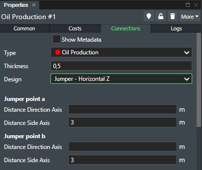
You have now the following jumper edit points for Jumper Point a and Jumper Point b as shown here and exaggerated for illustration purposes:
-
Distance Direction Axis - Adjust the numerical value for the distance length for the segment shown in the illustration above.
-
Distance Side Axis - Adjust the numerical value for the side offset for the segment shown in the illustration above.
The Jumper Point b values are identical for the other side of the Z Horizontal Jumper Connection.
Bridge
Creating a bridge is useful where you have crossings and need to elevate the connection to place assets such as Mattresses or Pipeline Crossing Supports.
Intermediary Point
This feature allows you change the type of the point to allow for creating a bridge. See how this is done:
Select the desired connection in the viewport and move the cursor along the connection until you reach the desired location. Then click the left mouse-button. The property panel Connections for the selected connection will then display the Intermediary Point options as shown here:
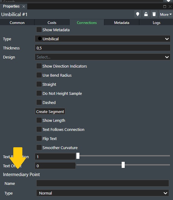
Name - Enter a name for the bridge or crossing.
Type - This specifies the type for the intermediary point. Normal is standard and will just be a typical intermediary point that allows you to modify the connection x,y position, but if you select Bridge from the drop down list this will then display new options as follows:
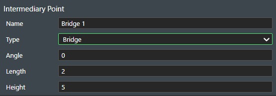
-
Angle - Enter the angle direction the bridge here in degrees.
-
Length - Enter the length of the bridge in either meters or feet.
-
Height - Enter the height of the bridge in either meters or feet.
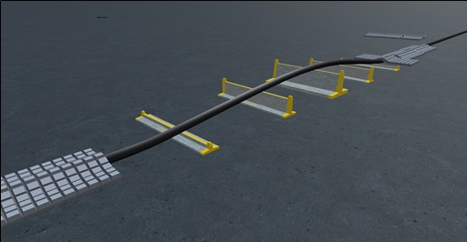
See the illustration below for an example of using the bridge feature:
Connection Segments
This feature allows you to add segments to connections meaning that you can define a connection to be comprised of multiple segments. This could be used to e.g. assign segments of a connection for indicating rock dumping, trenching, or if a connection is assembled with different types of materials e.g. parts of a mooring line could be chain etc. You define these in the Account Settings->Connection Segments.
When you have selected a connection on stage, you will find the following option in the connection section in project view as shown here:
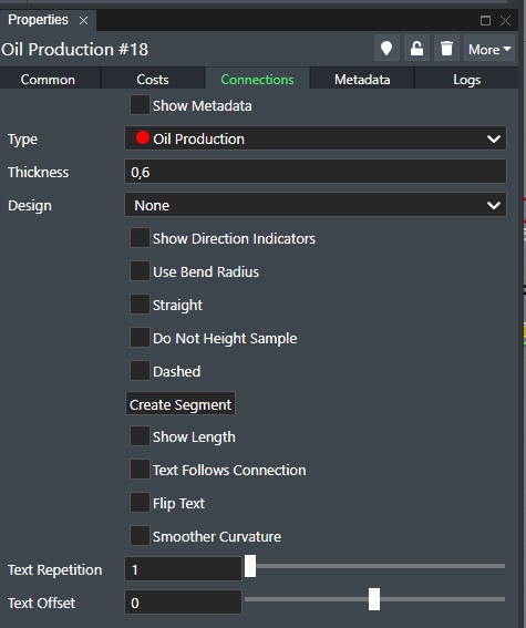
Press the Create Segment button to add a segment to the connection.
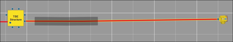
And the new segment will then be displayed on the selected connection as shown here:
You can click to select the segment on the connection. Doing so will display the cross hair edit points as shown below:
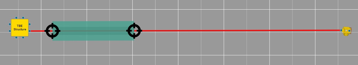
Clicking while holding down the left mouse button on the segment will allow you to move it along the connection to the desired position. If you click one of the cross hair selectors you can increase or decrease the segment length from that point.
In Project View you will then see a new segment entry appear under the selected connection as shown here:
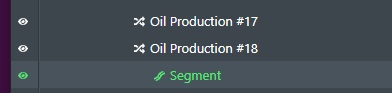
Selecting a segment under the connection entry will then display the segment property panels "Common", "Segment", "Logs" and "Metadata" if thats is defined under Account Settings->Connection Segments.
Common Tab
The Common Tab is comprised of all the available standard segment settings for selected segment(s):
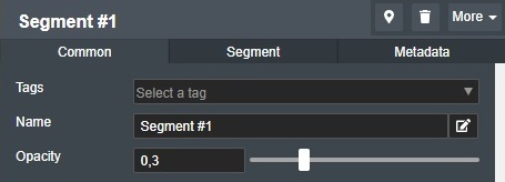
Tags - Every segment can be tagged which makes it easy to group selections. See Tags section for more information.
Name - To name a segment simply enter the desired name in the text edit box.
Opacity - The Opacity slider allows you to define the segment transparency value from 0,1 to 1. Where a value of 0.1 is fully transparent and a value of 1 is completely non-transparent.
Segment Tab
The Segment Tab is comprised of all the available specific segment settings for selected segment(s):
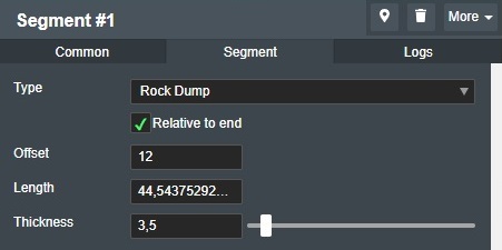
Type - If you have defined connection segment types in the account setting this drop down list will allow you to select the segment type. Please see Account Settings->Connection Segments.
Relative to end - Check this box if the selected segment is relative to the connection end point.
Offset - You can enter a numerical offset value from the connection end point to adjust the segment start point here.
Length - You can enter the numerical value for the length unit here.
Thickness - You can also choose the segment line Thickness or Width on an individual segment by entering the desired numerical value in the edit field to the right.
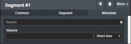
Meta data tab
If you have created associated metadata with the Segment Design Type under account settings, you will have the associated Metadata property panel:
Copy/Paste Metadata
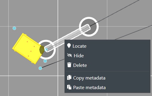
You can copy and paste Metadata between segments if metadata have been defined in the Account Settings for Segment Types. Right Click on the desired Segment to display the command menu:
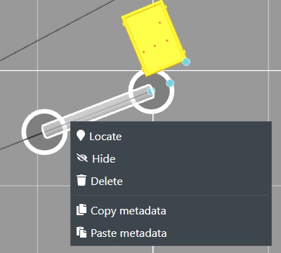
The select or multi-select the desired segments to paste the metadata to:
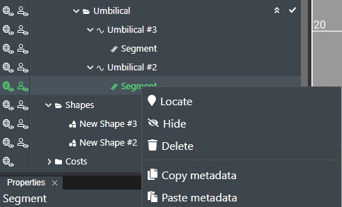
This functionality can also be done directly in Project View as shown here. Note! Multi-select copy and paste is much easier to do in the Project View window.
Logs Tab
See Logs Tab