Vector Layer
The new vector layer will be the layer that naturally includes our support for all kinds of vector elements and entities. The initial release enables you to create various shapes, but over time we expect to add other functionality such as markup, redline etc.
Shape Support
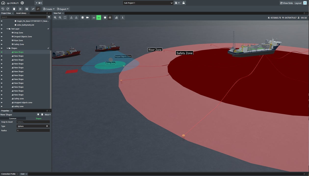
You can create vector shapes in FieldTwin Design. We support the following vector shape primitives in 2D and 3D: Box, Sphere, Triangle, Circle, Rectangle, Cone, Cylinder, Ring, Torus, Connection Tube, and Connection FlatTube. See the example illustration below on how this might be useful to your projects:
Create Shape
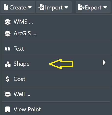
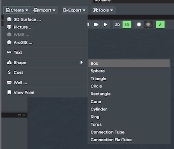
To create a new shape, select Shape from the Create Menu:
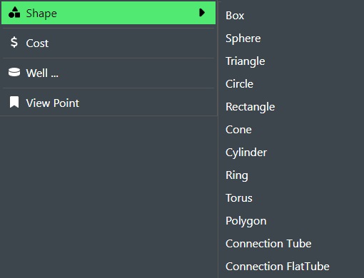
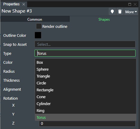
This will display a sub-menu of the available shapes as shown here:
Select the desired shape from the menu. This will display that you have entered the Shape command in the Viewport, and that you now can move the mouse to the location of your choice.
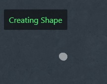
Once you have the correct location then click the left mouse button to create the shape at that position:
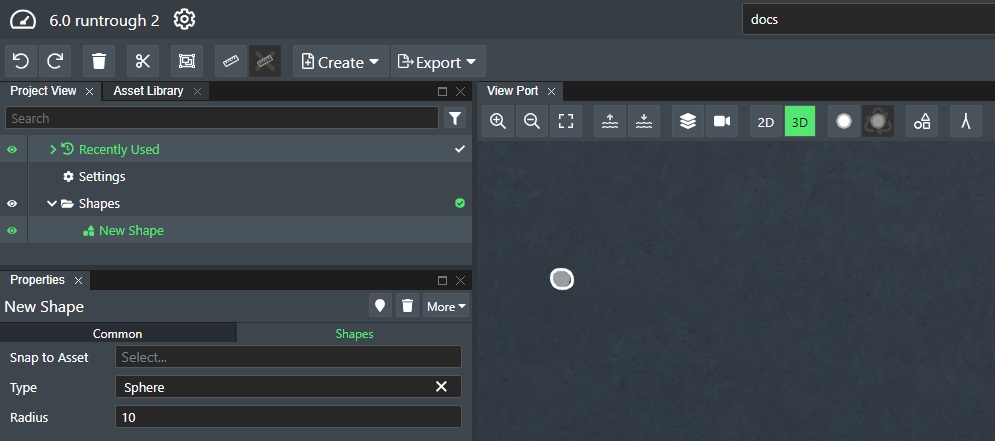
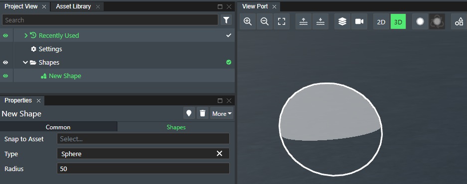
You will now see a new entry in the Shapes folder in the Project View tree called New Shape, and the corresponding New Shape property window with the Common and Shapes property panels. These panels allow you to set the various shape input values. For the Sphere we created above you can now change the Radius and in 3D view it then looks like this:
Edit Shape
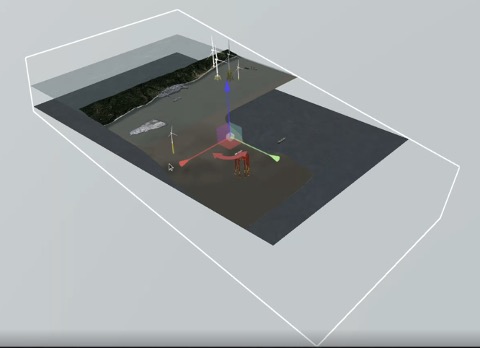
You can at any time edit the shapes you have created when it comes to positioning and rotation directly in the viewport in 2D or 3D. To edit a shape start by clicking on the shape. Once you have selected a shape, you will see the move/rotation helper tool in the center of the select shape as shown below:
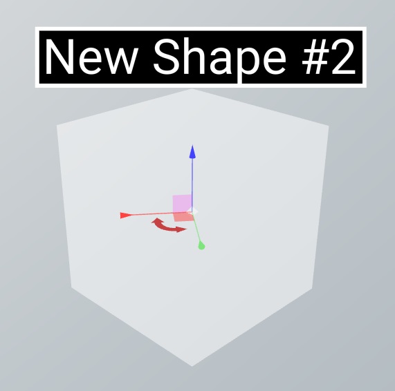
Select the red rotation arrow to rotate the shape in either direction. To move the shape up/down use the blue arrow of the helper tool, the red arrow allows you to move it sideways. Click outside the selected Shape to exit the edit shape mode.
Copy, Paste and Delete
You can copy and paste individual or a selection of shapes, by selecting then and then using the following keyboard commands:
| Key combination | Command |
|---|---|
| CTRL-C | Copy selected shape(s) |
| CTRL-V | Paste selection(s) at mouse location |
| CTRL-SHIFT-V | Paste selection(s) at same location |
| DELETE | Delete selection(s) |
You can copy and paste shapes between individual project tabs, and even copy paste individual shapes between different projects.
When pasting a shape it will appear where you have the mouse pointer positioned on the layout area. So if you want to paste multiple copies of an asset on stage simply move the mouse around to the desired position and press CTRL-V at each location. Use CTRL-SHIFT-V to paste in the same location as it remembers the exact coordinates.
Note! Shapes can naturally be selected and copy/pasted together with any other asset, connection etc.
Shape Commands
You also have a series of available commands for the shapes you create.
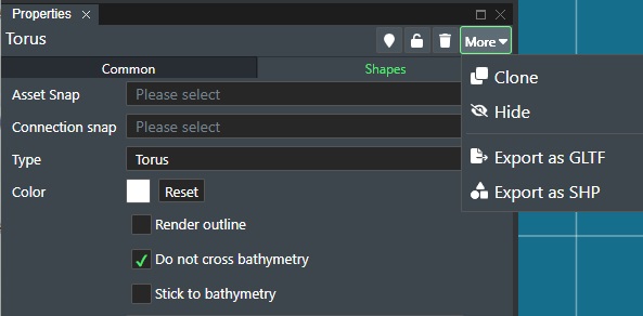
The commands as shown in the illustration above of the Torus shape propert toolbar from left to right are:
Locate - Click the locate icon to be taken to the shape location in the View Port.
Lock - Click on the padlock icon to lock the shape in place and disallow editing.
Delete - Click on the trashcan icon to delete the shape.
Clone - Select this from the menu to create a copy of the selected shape.
Hide - Select this from the menu to hide the shape in the viewport. Select Show from the menu to display it again.
Export as GLTF - Select this from the menu to export the shape to the GLTF file format. The file will be saved to your Download directory.
Export as SHP - Select this from the menu to export the shape to the SHP vector file format. The file will be saved to your Download directory.
Shape Properties
The various shape types have two (2) property panels when creating or selecting a shape namely Common and Shapes.
Common Properties
The Common property panel has the following settings as shown below using the Box shape as an example:
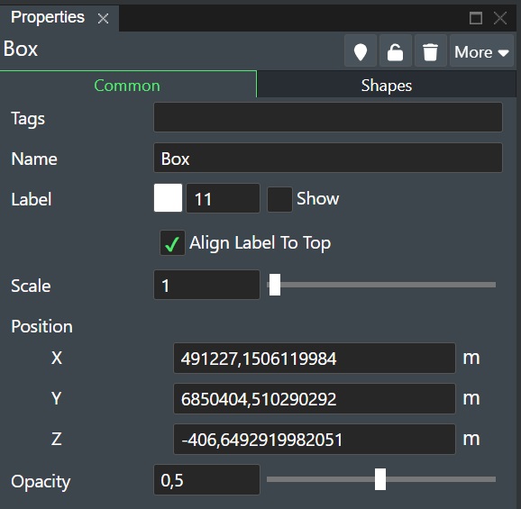
Tags - Any shape can be tagged with a user defined name e.g. Safety Zones. This makes it easy to create groups. Every item that share the same tag is automatically put in a folder under the Tags node in the Project View tree.
Name - You can assign a descriptive name for the shape here e.g. Safety Zone Drill Center.
Label - This will display a text box of the content of the Name field. You can change the font color and size by clicking on the colored box and use the edit field next to it respectively. Use the Show check box to select if the text should be On or Off.
- Align label to top - Check this box to align the shape label to the top of the shape.
Scale - Enter a numeric value to scale the asset or use the slider. Range is 0,1 to 100 with 1 as the default.
Position - The position of the shape can be adjusted.
-
X - This shows the current X coordinate of the shape and can be changed in the edit field.
-
Y - This shows the current Y coordinate of the shape and can be changed in the edit field.
-
Z - This is the Z offset coordinate of the shape and can be changed in the edit field.
Opacity - The Opacity slider allows you to define the shape transparency value from 0.1 to 1. Where a value of 0.1 is fully transparent and a value of 1 is completely non-transparent.
Shape Properties
The Shapes property panel has the following settings as shown below using the Box shape as an example:
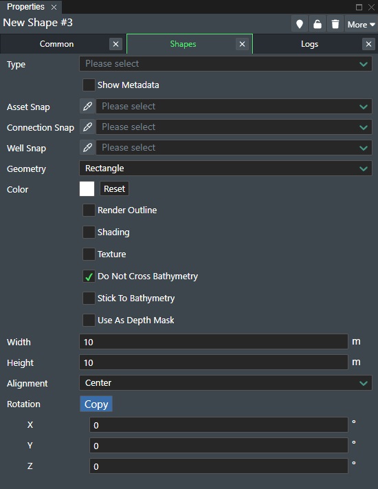
Type - This dropdown list allows you to change you shape to any of the supported types if they are defined in FieldTwin Admin under Object Settings. E.g. DropBox or Safety Zone etc.
Show Metadata - Check this box to display any metadata for the shape on stage.
Asset Snap - This will display a drop down list of all staged assets. Select one to have the shape snap to it.
Connection Snap - This will display a drop down list of all staged connections. Select one to have the shape snap to it.
Well Snap - This will display a drop down list of all wells. Select one to have the shape snap to it.
Geometry - You can change the shape geometry here from a drop down list of all supported shape types.
Use as Clipping Mask - Select this option to have the shape used as a clip plane(s) to cut through the View Port 2D/3D visualisation. This is very useful for presentations if you want to show your project with a view through your project layers.
Invert Clipping Mask - If the option above is selected you can also invert the clipping mask for the clip plane(s) to cut through the View Port 2D/3D visualisation. This is very useful for presentations if you want to show your project with a view through your project layers.
1 - Create a shape that is a box
2 - Select ‘Use as a clipping mask’ in the property panel
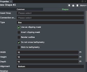
3 - Move your cube to cut your field where you like you can also input size, coordinates, depth, alignment etc. in the properties panel
Color - This is the default shape color. Click on the color picker to display the dialog where you can select the desired shape color. You can revert to default any time by clicking the Reset button
Render outline - Check this option to render the shape outline with the color set in the Outline Color selector.
Outline Color - This is the outline shape color. Click on the color picker to display the dialog where you can select the desired shape color. You can revert to default any time by clicking the Reset button
Shading - Check this box to enable shading effect on the shape.
Texture - You can assign a texture to the shape. This could be done on a e.g. Connection Tube and then choose texture type Rockdump to have the connection look like it has been rockdumped.
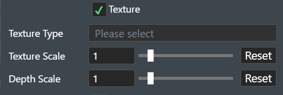
Texture Type - Select between Rockdump, Trench Backfill, or Pebbles in the drop down list.
Texture Scale - Enter a numerical value for scaling the texture. Range: 0,01 - 10, with 1 as the default value.
Do not cross Bathymetry - Check this option to prevent the shape Z value to go below the bathymetry e.g. the shape will always be above the seabed.
Stick to Bathyemtry - Check this option to have the shape Z value snap to the bathymetry e.g. the shape will always be fixed to the current seabed level.
Use as a Depth Mask - Check this option if you want to use the shape as a depth mask.
Width - Set shape width by entering the value in this field.
Height - Set shape height by entering the value in this field.
Depth - Set shape depth by entering the value in this field.
Alignment - Select the shape alignment by choosing either Top, Center or Bottom.
Rotation - The rotation of the shape can be adjusted.
-Copy - Copies the rotation values below.
-
X - This shows the current X rotation value of the shape and can be changed in the edit field.
-
Y - This shows the current Y rotation value of the shape and can be changed in the edit field.
-
Z - This is the Z offset rotation value of the shape and can be changed in the edit field.
Polygon Shape Properties
The Polgon shape properties differs from the other shape types and looks as in the illustration below:
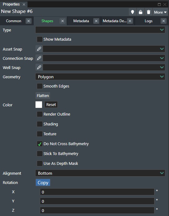
It has the following additional properties:
Smooth Edges - This will render the polygon as a spline.
Flatten - Press this button to flatten the polygon shape onto the bathymetry if the shape is over it.
Shape Types
You can change the Shape you want in the Types setting in the Shapes property panel. The following vector shape primitives are supported: Box, Sphere, Circle, Rectangle, Cone, Cylinder, Ring, Torus, Connection Tube, and Connection FlatTube.
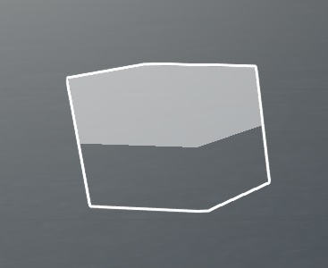
Box Shape
The Box shape will create a 3D box for you on the ViewPort e.g:
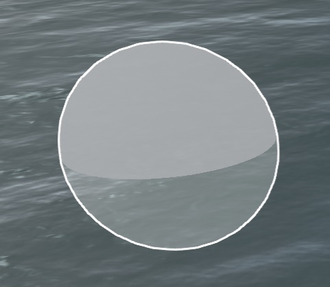
Sphere Shape
The Sphere shape will create a 3D sphere for you on the ViewPort e.g:
The Shapes property panel has the following different and/or additional settings as documented in Shape Properties:
Use as Point Light - Check this option to enable the shape to be used as a light source. You can then snap the shape to e.g. a ROV asset to provide an ROV light effect.
-
Light Intensity - Use the slider or enter a numerical value between (0,01 - 1) to control the light intensity. Click Reset buttonm to restore default value.
-
Light Decay - Use the slider or enter a numerical value between (0 - 4) to control the light decay. Click Reset buttonm to restore default value.
Enable Shadows - Check this option to enable a shadow effect for the shape.
Radius - Set sphere radius by entering the value in this field.
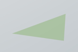
Triangle Shape
The Triangle shape will create a 2D triangle for you on the ViewPort e.g:
See Shape Properties for description of the available properties.
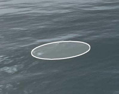
Circle Shape
The Circle shape will create a 2D circle for you on the ViewPort e.g:
See Shape Properties for description of the available properties in addition to the one below:
Radius - Set circle radius by entering the value in this field.
Rectangle Shape
The Rectangle shape will create a 2D rectangle for you on the ViewPort e.g:
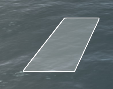
See Shape Properties for description of the available properties.
Cone Shape
The Cone shape will create a 3D cone for you on the ViewPort e.g:
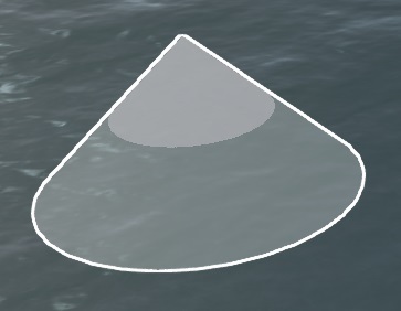
See Shape Properties for description of the available properties in addition to the ones below:
Use as Spotlight - Check this option to have the shape enabled as a spotlight. You can then snap the shape to e.g. a ROV asset to provide an ROV light effect.
-
Light Intensity - Use the slider or enter a numerical value between (0,01 - 1) to control the light intensity. Click Reset buttonm to restore default value.
-
Light Decay - Use the slider or enter a numerical value between (0 - 4) to control the light decay. Click Reset buttonm to restore default value.
-
Light Penumbra - Use the slider or enter a numerical value between (0 - 1) to control the light for the outer part of a conical shadow. Click Reset button to restore default value.
Cylinder Shape
The Cylinder shape will create a 3D cylinder for you on the ViewPort e.g:
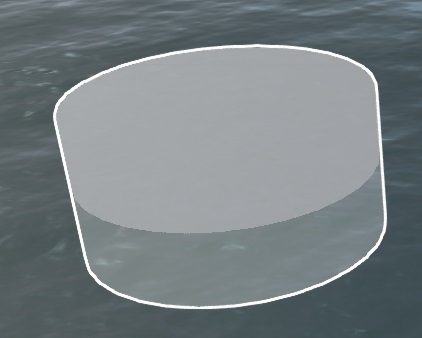
See Shape Properties for description of the available properties in addition to the ones below:
Radius Top - Set cylinder top radius by entering the value in this field.
Radius Bottom - Set cylinder bottom radius by entering the value in this field.
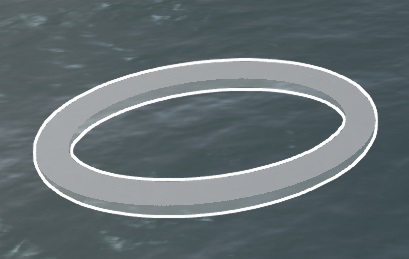
Ring Shape
The Ring shape will create a 2D ring for you on the ViewPort e.g:
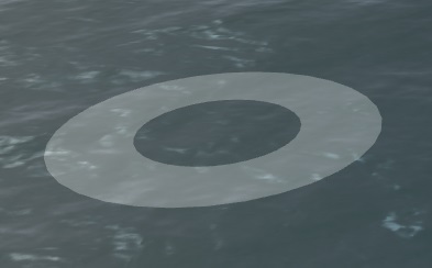
See Shape Properties for description of the available properties in addition to the ones below:
Inner Radius - Set ring inner radius by entering the value in this field.
Outer Radius - Set ring outer radius by entering the value in this field.
Torus Shape
The Torus shape will create a 3D Torus for you on the ViewPort e.g:
See Shape Properties for description of the available properties in addition to the ones below:
Radius - Set Taurus radius by entering the value in this field.
Thickness - Set Taurus thickness by entering the value in this field.
Polygon Shape
The Polygon shape will allow you to create a free form polygon on the ViewPort e.g:
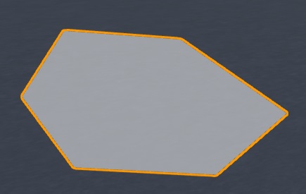
See Shape Properties for description of the available properties.
Connection Tube
The Connection Tube shape will create a 3D Tube for you on a selected connection in the ViewPort e.g:
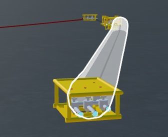
See Shape Properties for description of the available properties in addition to the ones below:
Smooth caps - Use this option if you want to smoothly taper of the end of the connection tube.
Radius - Set the Connection Tube radius by entering the value in this field.
Full length - Uncheck this option if you do not wish this shape to follow the entire connection. This will display the following new parameters:
-
Relative to end - This will anchor the start the shape at one of the endpoints.
-
Offset - Enter a numeric offset value from the endpoint to move the shape position.
-
Length - Enter a numerical value to set the length of the shape.
Note! - You can select the shape in the viewport and drag it to position it as well.
Connection FlatTube
The Connection FLatTube shape will create a 2D Tube for you on a selected connection in the ViewPort e.g:
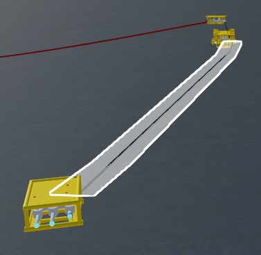
See Shape Properties for description of the available properties in addition to the ones below:
Smooth caps - Use this option if you want to smoothly taper of the end of the connection tube.
Radius - Set the Connection Tube radius by entering the value in this field.
Full length - Uncheck this option if you do not wish this shape to follow the entire connection. This will display the following new parameters:
-
Relative to end - This will anchor the start the shape at one of the endpoints.
-
Offset - Enter a numeric offset value from the endpoint to move the shape position.
-
Length - Enter a numerical value to set the length of the shape.
Note! - You can select the shape in the viewport and drag it to position it as well.