Getting Started
Main commands
After you log in you will be presented with the following available commands in the vertical left hand side toolbar as shown below:
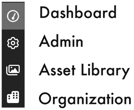
Learn more about Dashboard, Admin, Assets, Organization options.
FieldTwin
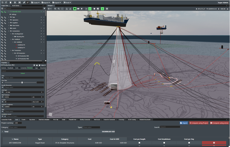
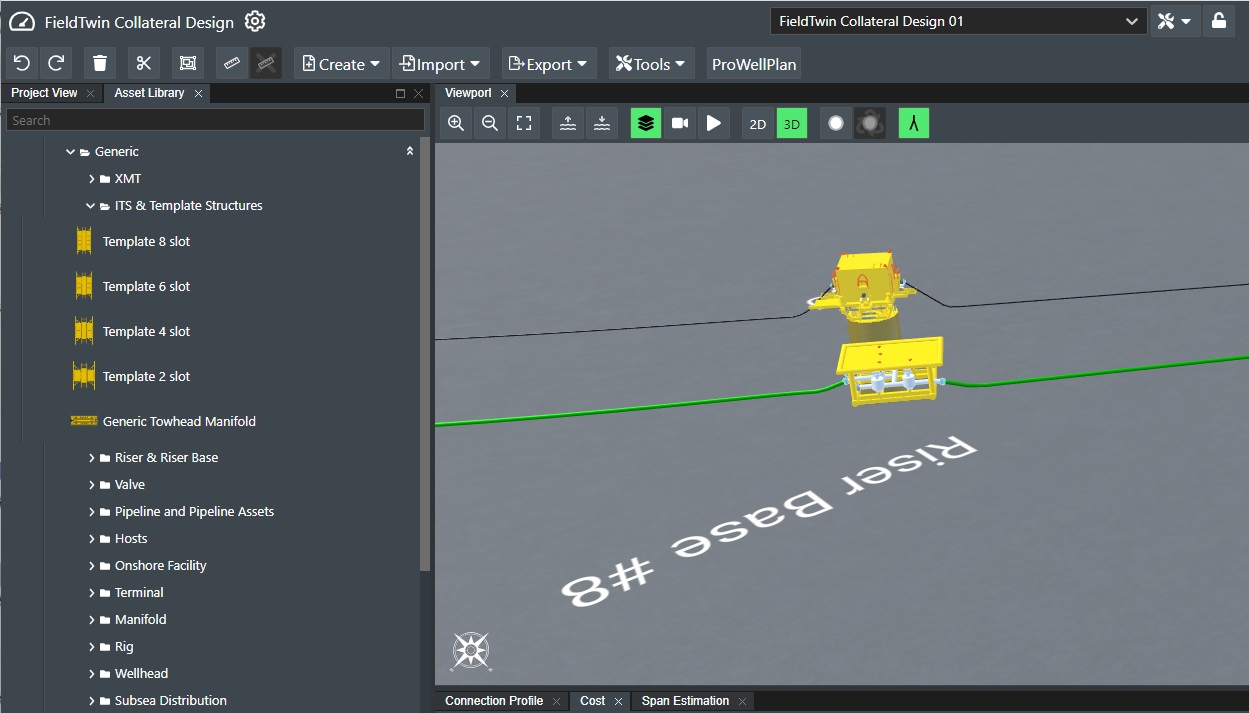
FieldTwin allows you with quick and easy "drag and drop" operations to create new or replicate existing field layouts in a very short time. Connecting assets are as simple as drawing lines/splines between asset/structure connection points. The layouts can be as simple or as advanced as your imagination allows. See a field layout example shown in the screenshot below:
Project Toolbar
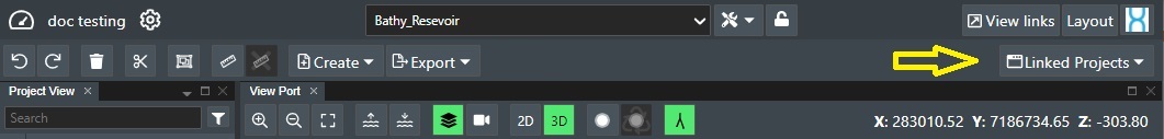
The topmost toolbar is the project toolbar for your current project.

On the left side of the toolbar you will see the following icons before and after your Project Name:
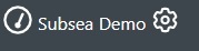
The icon to the left of the project name will take you back to the Dashboard.
The cogwheel icon to the right of the project name will take you to the Project Settings
Active Users
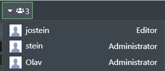
The following is the real time presence indicator for the current sub-project that shows the number of active users right now:

Click on the presence indicator to display the list of current active users and their user role:
Sub Projects
For every project, you can create as many sub-projects you want. This is useful when you operate with different layout designs that you may want to contrast or compare against each other, or to show various stages of the field life cycle.

This will present a drop down list where you select the sub-project to load by clicking on the desired name.
Sub Project Commands
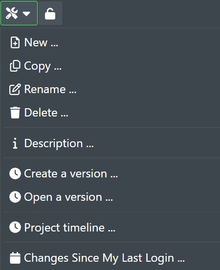
To see the available commands for sub projects, click on the tools icon as shown here:

This is a drop down list for the available sub project actions namely New, Copy, Rename, Delete, Description, Create a version, Open a version, Project timeline, and Changes since my last login.
New sub-project
You can easily create several versions of a project, or sub-projects (views) if you will of a field layout for the same project by using the New command. Simply press the New button on the top toolbar. This presents the following dialog allowing you to "Add sub-project".
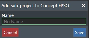
Simply type in the name for the new sub-project, and press "Save". This will create a new Sub-project. Or press "Cancel" to abort!
You can also create folders to group your sub-projects. To do this Use "/" in the project name field to create the folder. E.g. /Folder1/Folder2/Project Name
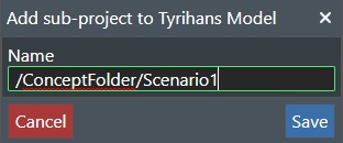
This will then give you a folder structure such as shown here (This will also create folders in the dashboard):
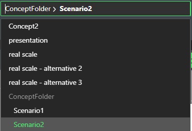
You can switch between the various Sub-projects by selecting from the sub project drop down list.
Copy
If you want to create a copy of the active sub-project, you can keep the suggested name which is starting with new copy or simply write in the new desired name in the New copy name field. The Target project drop-down-list is set to your current project by default, but allows you to copy your current sub-project into any another project in your tenant, which is very useful if you want to reuse the current field layout/sub-project again in another project.
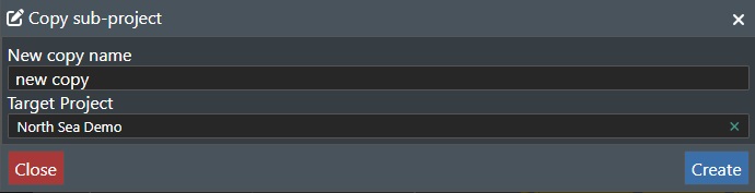
Then press the Create button to start the process, or press the Close button to exit.
Rename
This will allow you to rename your sub project or branchy and selecting this option will present the following dialog:
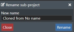
To rename a sub-project or simply change the name in the New name text edit box and press Rename. Press Close to abort.
Delete
To delete a sub-project simply press the Delete command. The following dialog will be presented:
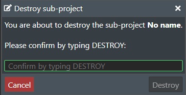
Type Destroy in the text box for final confirmation, and then press the Destroy button to delete the sub project. Press the Cancel button to abort.
Note! This action cannot be undone!
Description
You can add project information for the current sub-project, by pressing selecting this option. This will present you with a new dialog where you can add text/notes describing the current sub project.
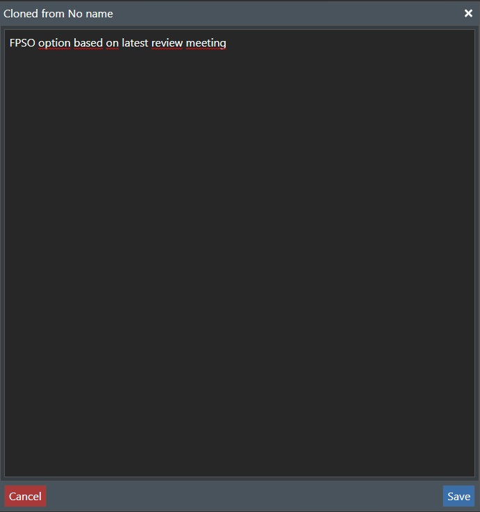
Enter the desired text and press Save or Cancel to exit.
Create a version
You can at anytime create a version of the current viewed project by using this command. This will create a version bookmark in the event stream that allows you to go back to this specific version stamp at any time.
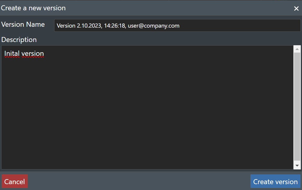
Version name - This field is populated automatically with the current date, time and user email address, but you can change it to your version nomenclature of choice.
Description - You can enter your version description here with additional information as needed.
Press Create version to create the version, or Cancel to abort.
You will also see the full Version List of sub projects in your Dashboard
Open a version
This command allows you to open any version of the project that has been created by the Create a version command.
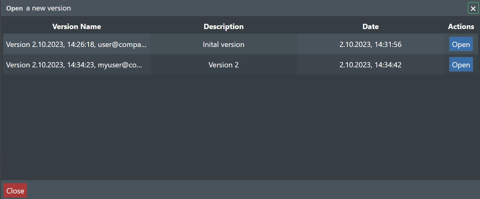
Select the desired version from the list above, and press Open to launch a new browser window with that version, or press Close to abort.
If you selected Open the new browser window will show the version in View Only mode, and you will see the version info displayed in red in the toolbar.

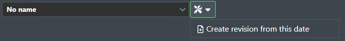
You can however select the following command:
Create Revision from this version - Select this to create a new project from this version as shown below:
This will then display a new dialog box as follows:
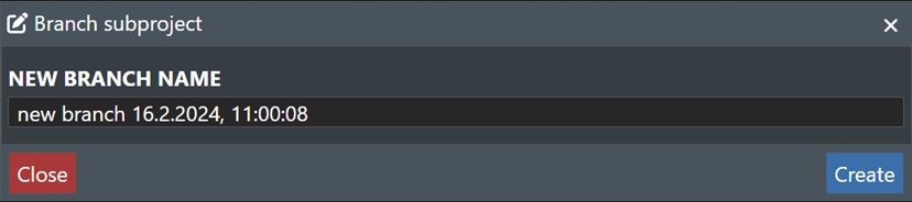
Press Create to create a new project branch, or Close to abort.
Project timeline
This command allows you to go back in time to any date and timestamp from the project creation date until present.
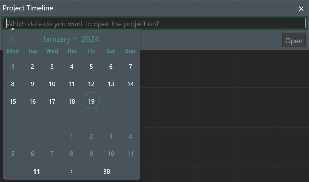
Select your date by using the date picker and then select the desiered time for that day using the controls at the bottom of the date picker as shown in the illustration above. Then press Open to launch a new browser window with how the project was at that point in date & timestamp, or press Close to abort.
If you selected Open and view the project from the desiered date/time selected in View Only mode, you can now select the Create Revision from this date as documented previously above.
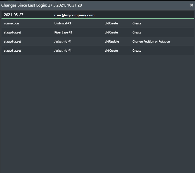
Changes since last login
Selecting this command will display a dialog box with a list of all changes made to the sub project since you last logged in so you can see what other users have done in the project.
Lock Sub project

The Lock button toggles the current sub-project between locked/unlocked state if you want to e.g. put the current (sub-)project in a locked state where no edits can be made. Click again to unlock it.
View Links
The View Links feature allows you to generate a URL for the current sub-project that can be distributed externally to non FT Design users even outside your organisation in e.g. emails, as an image URL in MS PowerPoint presentations etc. You control the “View limit” count and “Valid until” date to distribute a link to external non FT Design users. The default water opacity can be set along with the outline of disconnected connections in red to better display the project as the user wants it to be displayed.
When the recipient(s) click on the URL they will be able to view the shared sub-project directly in their browser, and switch between 2D and 3D view. This view allows them to zoom, pan around and look at your design in full resolution. No other information such as cost, meta data etc. are attached and thus will not be visible. The company logo set in your account settings will also be included.
With FT Design real time collaborative capabilities, you can also be on the phone with the recipient of the link and then from your own browser drive the session and take them through the layout and interact with it at will to show more details.
Pressing the "View Links" button on the toolbar will display a dialog as shown below.
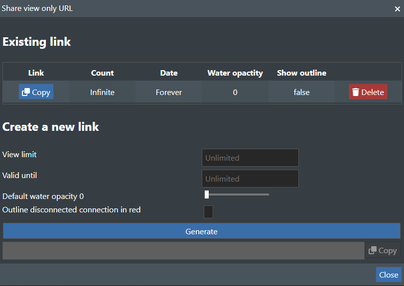
This brings up the "Share View only URL" dialog box where you can create new shareable links, and also see which links have already been shared. They can also be deleted. You can set the share link validity by selecting the number of views and/or the date range for when the link is valid. See illustration below:
Create a new link
View limit - Set a numeric value for the number of times the link can be viewed before expiring. If you leave this field blank it means that number of views are unlimited.
Valid until - Specify the expiration date for the link. If left blank there is no expiration date.
Default water opacity - Use the slider bar to set the default water opacity level (0-100) for the view link.
Outline disconnected connection in red - Check this option for the view link to display all non connected connection in red for clarity.
Use user visibilty - Check this to use the same visibility options as you have when generating the view link.
Generate - Press this button to generate the shareable URL for the project.
As soon as you have generated a shareable link for the first time for a specific sub-project the dialog will change appearance as shown in the illustration below:
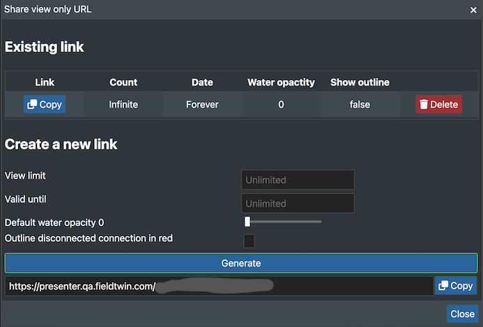
It will then display the following new information:
Existing link
This will list all existing created links for this sub-project. For each of these you can:
-
Copy - This will copy the link to the clipboard so you can paste it elsewhere.
-
Delete - This will delete the link.
and you will also see a copy of the created link under the Generate button, where you can do a Copy as described above. Press Close to exit the dialog.
Layout
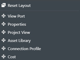
The Layout button will display a list of all the default module windows registered with the application as shown here:
If you have closed any of the module windows, you can select it from this list to make it visible again.
View Port - Select this to create multiple Viewports that you can rearrange on the screen and select to be in either 2D or 3D.
Properties - Select this if the properties tab has been closed and you want to make it visible again.
Project View - Select this if the Project View tab has been closed and you want to make it visible again.
Asset Library - Select this if the Asset Library tab has been closed and you want to make it visible again.
Connection Profile - Select this if the Connection Profile tab has been closed and you want to make it visible again.
Connection Designer - Select this if the Connection Designer has been closed and you want to make it visible again.
Cost - Select this if the Cost tab has been closed and you want to make it visible again.
Reset Layout - Select this to reset all the module windows to their default setting.
Notifications

Click on the Notifications icon to bring up the menu option for it as shown below:
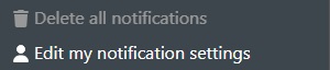
Delete all notifications - Select this to clear all notifications from the list.
Edit my notifications settings - Select this to display the notification setting dialog.
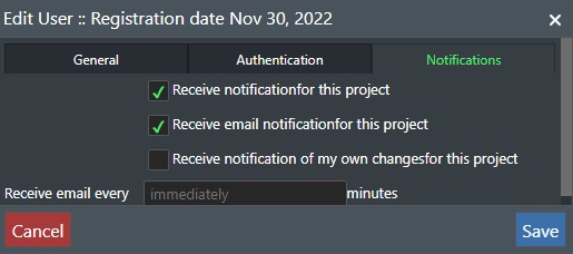
This will display the Edit User dialog with the Notification Tab selected:
-
Receive notification for this project - Check this to recieve any notifications for this project.
-
Receive email notification for this project - Check this to recieve any notifications for this project as an email.
-
Receive notification of my own changes for this project - Check this to recieve notifications of changes you have made for this project.
-
Receive email every - Set the frequency for email notifications. Default is immediate.
Press Cancel button to exit without changes, or Save to update your settings.
User Menu
The rightmost icon on the project toolbar will display the user menu as shown here:
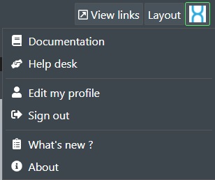
The user menu gives you access to functions for Documentation, Help desk resources, User Settings etc. See User Settings for more information on all options.
Main Toolbar
You will find the main toolbar located below the project toolbar with the following icons:

The functionality of the toolbar is comprised of the following commands:
Undo / Redo

Undo or Redo up to the last twenty (20) operations. You can also press CTRL-Z for Undo, and CTRL-Y for Redo.
Delete Selection

Will delete the selected object(s).
Cut Connection

After selecting the cutting tool, click on the desired connection you want to cut. This will cut the connection at the click location and create two individual connections.
Multiple Select

Toggles the selection rectangle for multiple asset/connection selection. This allows you to easily move all selected objects to a new location. If you select just connections, every connection that intersects with the multiple selection area will be selected. Once the selection is complete, you can click on one of the selected connections and move the entire selection set around and all connections will follow. Press and hold down the "CTRL" key and the click on individual assets/connections to add/remove it to/from the selection.
You can also press and hold the SHIFT key down at anytime in the Viewport to invoke the multiple select command.
You can of course also copy/paste, delete and rotate the selection.
| Key combination | Command |
|---|---|
| CTRL-C | Copy selection |
| CTRL-V | Paste selection at mouse location |
| CTRL-SHIFT-V | Paste selection at same location |
| DEL | Delete selection |
| CTRL + Click | Add asset/connection to selection |
| SHIFT | Hold SHIFT down to invoke multiple select |
| CTRL | Hold own CTRL key to rotate the selection |
Note! You can copy and paste selected item(s) between different projects and sub-projects.
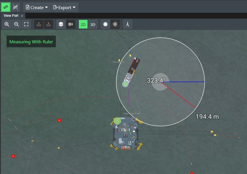
Measure Tool

Enables the measurement tool that allows you to measure the distance in the selected unit system and view the angle between 2 selected points in the stage. The measurement function will stay active until you select the "Clear Ruler" icon. To start a new measurement, simply click on a new point you want to measure from. The radius can be determined for e.g. ships or installations for different purposes such as safety distance.
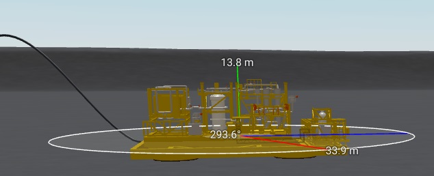
If you measure in 3D mode we will also display the height when you move the nouse along the Z axis after completing the measurement circle as shown below:
Create Menu
The create drop-down menu allows you to add content or online services to your project as shown in the following menu:
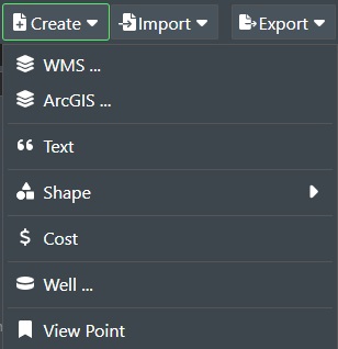
See the Create Menu documentation for more information on each command.
Import Menu
The Import drop-down menu allows you import content into your project as shown in the following menu:
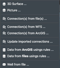
See the Import Menu documentation for more information on each command.
Export Menu

The Export drop-down menu allows you export content from your project as shown in the following menu:
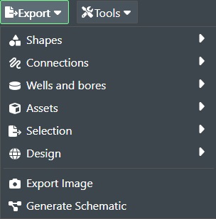
See the Export Menu documentation for more information on each command.
Tools Menu

The Tools Menu will have various utility commands that can be executed on the current project loaded.
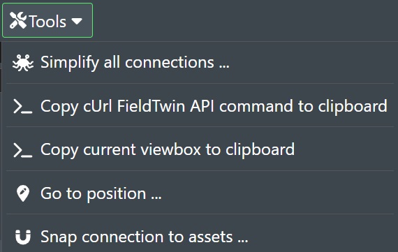
Simplify all connections - Select this option to run a simplification algorithm on all connections in the project by removing the number of intermediate points to improve performance. This option can also be involved from the right click menu on a selected connection or selection of connections, or when importing data from file or WFS servers.
>_ Copy cUrl FieldTwin API command - This will copy the project link including selected items that can be shared with support or help you debug.
>_ Copy current viewbox to the clipboard - This will copy the current viewbox x,y,z coordinates to the clipboard that can be shared with support or help you debug.
Go to position - Allows you to navigate a big field layout or verify assets etc. with a list of coordinates as well.
Selecting this option will present the following dialog box as shown below:
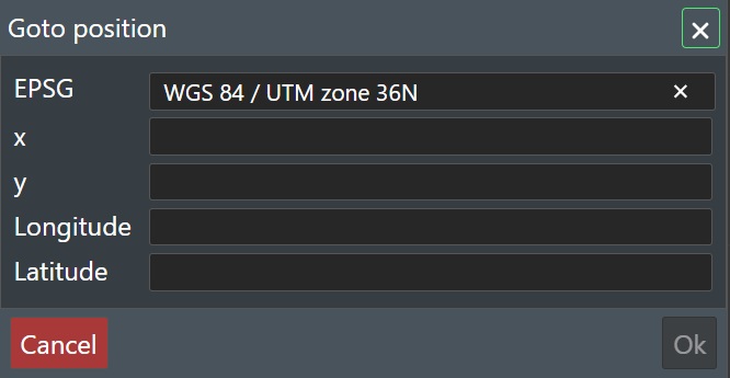
Select the EPSG from the drop-down list if not set in project settings already. Then enter the desired X,Y position and FT will transform that into Lat/Long coordinates automatically, and vice versa if you enter Lat/long coordinates. Press “OK” to be taken to that coordinate in FT, or press Cancel to abort.
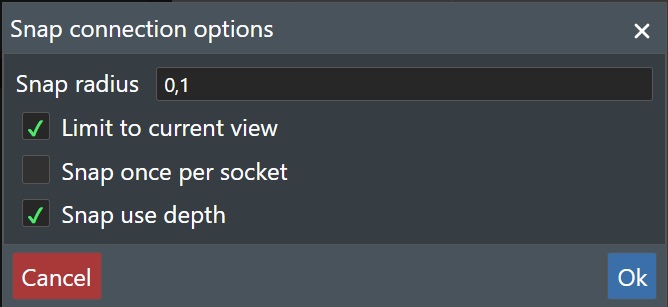
Snap connection to assets - This will allow you to automatically snap unconnected connections to assets based on radius. Very useful if you import a series of connections and then you do not spend time on connecting each one manually.
Selecting this option will present the following dialog box as shown below:
-
Snap radius - Enter a radius value in meters. Then FT will automatically snap any unconnected “Connections” to the nearest socket for an asset within the set radius.
-
Limit to current view - Check this option if you only want the snap operation to happen to the connections currently shown in the Viewport.
-
Snap once per socket - Check this option to ensure that only one (1) connections snaps onto each asset socket.
-
Snap use depth - Check this to also use the depth value of the connection endpoint along with the radius to determine the snap operation selection.
-
Snap using selection - Check this to include all staged assets and connections for the snap operation..
Linked Projects
You will only see the Linked Projects drop down list in the toolbar as illustrated below if you open a sub project that has been linked to another child project:
Click on this to see a list of the project the current sub projects are linked to e.g.:
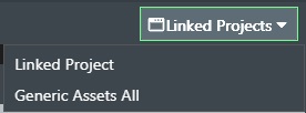
Selecting an entry from the dropdown list will then open that child project directly.
License Type
This indicates if you are running a PRO Design, PRO, or View license as shown below for a Pro Design user.
View Port
The View Port is your drawing canvas where you do your field layout design work as shown in the illustration below:
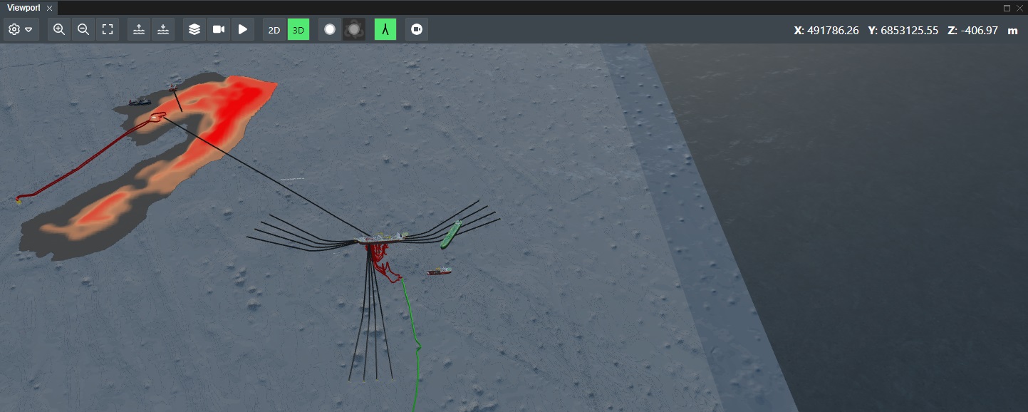
View Port Coordinates and CRS
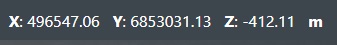
When you move the mouse cursor around the view port the View Port toolbar will show the current x, y, and Z coordinate as well as the CRS (Coordinate Reference System). Note! The Z coordinate will be equal to the project Sea bed level value unless Bathymetry data is loaded for the project. If that is loaded then the current Z value of the Bathymetry data in the X, Y position will be shown.
We support real world coordinates that allows you to start designing a field layout without having to load “Bathymetry” data first to set a position. You can correctly place you topside/subsea assets at their designated location directly by entering in the x,y coordinates and set the heading when an asset is selected.
View Port Toolbar

The View Port toolbar has the following commands
View Port Settings
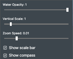
This drop down settings menu gives you quick access to some of the viewport settings:
Water Opacity - The Opacity slider allows you to define the water transparency value from 0,1 to 1. Where a value of 0.1 is fully transparent and a value of 1 is completely non-transparent. Note! This applies to 3D view only.
Vertical Scale - The vertical scale slider allows you to scale the positions of all layers relative to the water. The default setting is 1 (100%).
Zoom Speed - Allows you to change the zoom speed sensitivity if you are using trackpads or similar touch input devices.
Show scale bar - Check this option to show the scale bar helper in the Viewport in 2D mode to better gauge distances.
Show compass - Check this option to show the compass rose directional helper in the Viewport in 3D mode to indicate spatial view orientation.
For all the available View Port settings, please see View Port Settings
Zoom In / Zoom Out

Allows you to zoom either in or out on the current viewport.
Zoom Extent

Automatically zooms the view outwards to fit all present assets/vessels/connections on the stage.
Topside / Subsea

Will move the camera view topside e.g. above sea level, or subsea e.g. below sea level.
Reservoir Mode
By combining information sources such as reservoir horizon scans and well trajectory data with your visualised field layout in 3D you immediately obtain a better understanding of the complete project.

Enables the 3D Reservoir mode for showing the real reservoir data in 3D with any loaded well trajectories. Additionally, you can also see the real world position of both the top and bottom hole for each individual well.
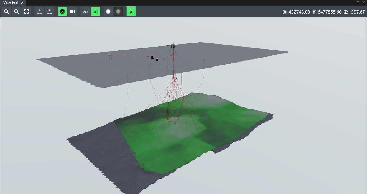
When the Reservoir mode is enabled the seabed will turn translucent to allow you to view layers and/or 3D data that are positioned below the actual seabed level e.g. the reservoir data sources.
With 3D data is loaded in it is placed as an individual layer. But unlike standard bitmap layers you can only manipulate visibility on/off and opacity. This is because the correct scale, position and rotation is embedded in the converted 3D data and is correctly represented in real world scale.
Typical data that can be displayed beneath the seabed is for example:
Reservoir maps
Well placing maps
Geological formations
3D scan of reservoirs
3D well trajectories
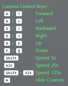
Flythrough Camera
Enables Flythrough Camera Movement for 3D Viewport mode, which is useful for screen recordings or live presentations.

To navigate in the Flythrough camera mode use the following keyboard commands:
Play Animation
This starts the animation of staged assets that have animation frames such as e.g. Wind Turbines with rotating blades etc.

2D / 3D Mode

Press the 2D icon for 2D view and 3D icon for 3D view.
FieldTwin Design is completely 3D driven from a rendering perspective, but a 2D Mode is still available for field layout design, but is then represented by the camera showing a top-down perspective of the view port so you get the 2D experience if desired.
You can also quickly switch between viewing the view port in 2D or 3D Mode respectively by using the following keyboard shortcuts.
| Key combination | Command |
|---|---|
| 2 | 2D View Mode |
| 3 | 3D View Mode |
Edit Connection Point

Select the Edit Connection Point icon to be able to change the location of an existing connection point, or to create a new connection point. If you click on an existing connection point you will be able to edit that. If you click somewhere else a new connection point will be created. Once selected or created in either 2D or 3D mode and you will see the move/rotate functionality appear that allows you to move/rotate the connection point.
Doing this in 3D makes it easy to attach connection point in the right height on an asset. Click the icon again to stop the edit mode.
Note! - You can also edit connection points directly without being in Edit Connection Point mode simply by right clicking the connection point.
Read about changing attributes for Connection Points.
Copy / Paste Connection Point
When you are in Edit Connection Point mode and have selected a connection point you can now copy and paste it with the following keyboard commands:
| Key combination | Command |
|---|---|
| CTRL + C | Copy the selected connection point |
| CTRL + V | Paste the copied connection point |
Any attributes and metadata already assigned to the selected connection point will be copied along with it when pasting it.
Reset Connection Point

If you select an asset that has had connection point added, this icon is now available for selection. If you click it then it will reset the connection point to default.
Connection Point Metadata
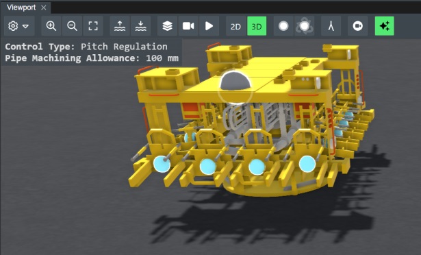
When you move your mouse pointer over a connection point that has metadata assigned to it then the metadata info will now automatically be displayed on screen in the top left corner of the View Port as shown below:
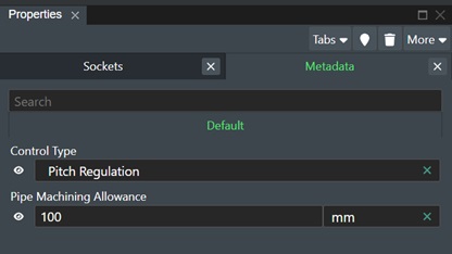
And if you right click with the mouse on said connection point then the Metadata Properties panel will automatically be displayed for easy editing:
Smart Model Docklets
When using smart models from the Asset Library you will now see the smart model docklets (Model Attchement Points) visualized with green circles as illustrated below:
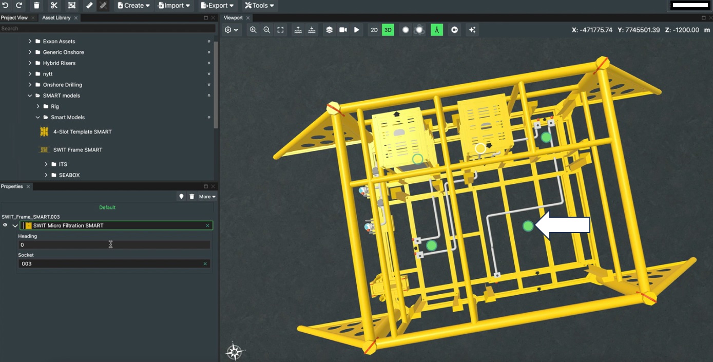
Selecting one of them will display the associated Property Page which will then display the following options as shown below:
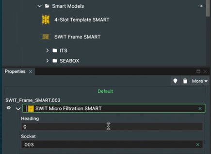
Available Models - This drop down list will display the smart model sub components then can be attached to the selected docklet.
Heading - Allows you to adjust the heading of the smart model component in degrees (0 - 360).
Socket - Allows you to change the socket enumeration if needed.
Show / Hide Wellbores

Click this icon to show or hide any loaded wellbores in 2D / 3D mode.
Record Video

This option gives you the opportunity to record a video of your project. This is very useful for presentations since you can show only the desired parts of your project and it does not need to be a live demo. Also, it can be included in any presentation, allowing other people that are not experts in the software to demonstrate it.
Click on the Camera icon to start recording. The camera icon will then turn green. Now you can navigate around the project while the viewport is being recorded. To stop recording simply click on the Camera icon again. This will then display a dialog with the option to save your recording.
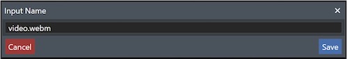
Type in the desired file name and press the Save button and the video file in WEBM format will be stored in your download folder. Press Cancel to abort.
Pretty Mode

By enabling this mode FieldTwin auto selects the most common visual effects for you that are useful for presentation and marketing purposes. See below for an example:
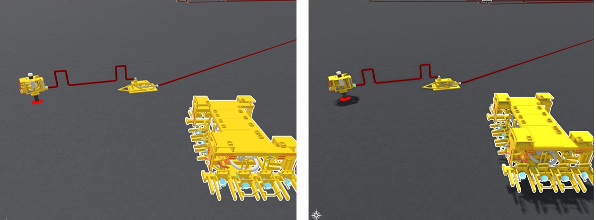
The rightmost image shown has Pretty Mode enabled and you can see shadow and light effects etc. are turned on. You can read more about all the visualization effects available in FieldTwin here World Settings
Assets
The first step after completing the Add Project command to create a new project is to start designing your field layout! To populate your field layout you need to choose your structures from the Asset Library which by default is positioned on the left side of the screen.
You will see the Asset Library tab just next to Project View This will reveal the asset library selector catalog. You can have multiple asset libraries including private asset libraries for your own company that depicts your own equipment or vessels. Default libraries available are "Generic" and "User" libraries. The generic library is comprised of the most common subsea and topside assets and in addition various vessels. The "User" library is comprised of your own defined assets that have been added into this library from the asset editor.
To add an asset to your field layout design in the Viewport area simply click it and hold down the left mouse button while you drag it out of the asset list and onto the Viewport area and release the mouse button. To reposition the asset just click again on the active asset and hold the left mouse button down while you move it to the new position on the Viewport and release the mouse button.
Copy and Paste Assets
You can copy and paste individual or a selection of assets/connections, by selecting then and then using the following keyboard commands:
| Key combination | Command |
|---|---|
| CTRL-C | Copy selected asset |
| CTRL-V | Paste selection at mouse location |
| CTRL-SHIFT-V | Paste selection at same location |
You can copy and paste assets between individual project tabs, and even copy paste individual assets between different projects.
When pasting an asset it will appear where you have the mouse pointer positioned on the layout area. So if you want to paste multiple copies of an asset on stage simply move the mouse around to the desired position and press CTRL-V at each location. Use CTRL-SHIFT-V to paste in the same location as it remembers the exact coordinates.
Move Asset
You can easily move an asset by first clicking on the desired asset. To "Move", simply hold the left mouse button down while you move the asset to your desired location and release the button.
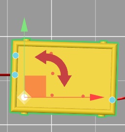
Rotate Asset
Once the asset is placed in the Viewport you will see a rotation indicator next to it:
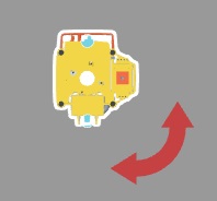
- Rotate - Click and hold down the left mouse button on the Rotate icon to change the Heading of the asset in degrees (0-359). You can also set this in the Asset Common tab using the Heading input.
Delete Asset
To "Delete" an asset, simply click on the Trashcan icon or the delete key on your keyboard, and the asset will be removed from the stage.
Replace Asset
This command allows you to easily replace one or more assets with another. You select the option by right clicking on the asset on stage or in Project View. This will display the following dialog box:
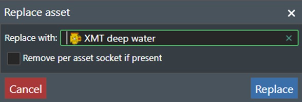
Select the replacement asset from the drop-down list and narrow the list with search criteria if needed.
Remove per asset socket if present - If you have defined sockets on a staged asset this option will reset that.
Note! To replace multiple assets at once, you need to do a selection first
Connect Assets
FieldTwin Design comes with a set of the most typical generic subsea and topside assets that can be used for both simple and complex field layouts. Most of these assets can be connected to each other as would be expected for a field layout.
The number of asset connection points depends on the asset you have selected. They can be edited using Edit Connection Point command or in the asset editor if you have the admin privileges. Connection points are represented by the blue circles as shown below:
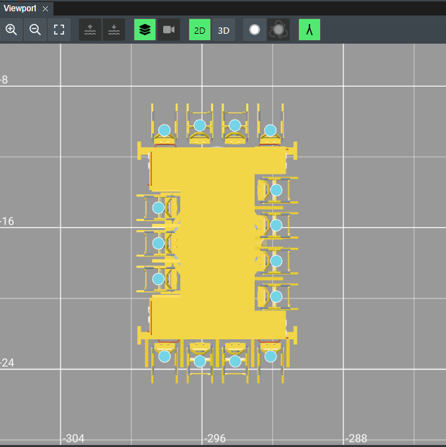
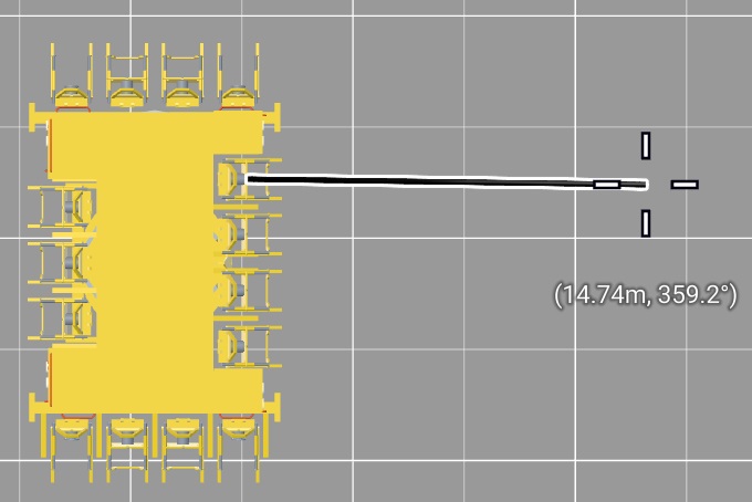
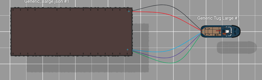
To make a connection between two (2) assets or structures you need to click once on the starting connection point once the mouse cursor changes to a "cross selector". Then move the mouse over to the asset connection point that you want to connect to and click once again when the "cross selector cursor" is shown. The assets will then be connected together.
When you start to draw a connection the length (distance unit) and direction (angle) will continuously be shown on the stage until you complete the connection.
Note! You can have as many connections between structures as you want such as shown here:
No connection when asset is selected
If this option is selected under the stage settings you will not be able to make a connection on an asset, when the asset is in selected mode. If you uncheck it then you can make the connection regardless of the asset state.
Edit Connections
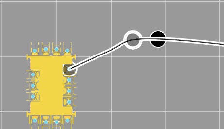
If you click on the connection itself between two assets, you can add curvature edit points, which allows you to modify the layout of the connection. You will see an outlined circle symbol when you move the cursor along the connection. At the desired location click the left mouse button. You have now added an edit point that you can move around to modify the connection curvature.
To remove an edit point from the connector press and hold the "Shift" key and select the edit point on the connector.
To remove a connection, click on the "Trashcan" icon in the toolbar as illustrated below, or press the Del key.
Join Two Connections
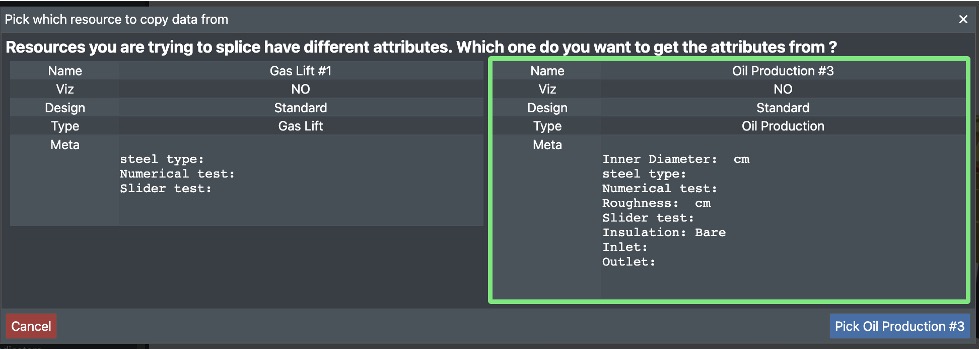
You can ‘splice or join’ 2 connections that have been cut before or 2 connections that have never been connected.You can display different connection types and individualised metadata for each connection. The system will ask you to select the data types that apply to the new connection that is generated.
1 - Select a connection by clicking on one of the end points, then drag the end point onto the end of ‘connection 2’.
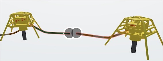
3 - When you release the mouse, the points will ‘merge’ and if connections are different, a dialog box will ask you to select the data you wish to apply to the new connection.
4 - Click on the attributes you want to keep and click on ‘Pick Connection name’.
5 - You can then check the property panel for the connection attributes.